With HIGHVOLT’s new power supply platform for test equipment, a power electronic supply unit is now available for the first time—marking another step forward into the future of power supply technology.
Text: Martin Buschendorf
New developments and technological progress change our lives. Long-distance calls made from a phone booth or phones with a rotary dial are now just a chapter in the history books. Nowadays, almost everyone uses a smartphone and couldn’t imagine life without the huge range of functions besides phone calls that these devices offer. Another change that is familiar to us all today is the move from the combustion engine to the electric car.
The Reinhausen Group has seen its own fair share of developments—drawing boards for designing on-load tap-changers or testing technology are yet more examples of things that have been consigned to the past. In fact, technological progress has taken hold across every industry, and conventional systems are being replaced with smart ones. As a global technology leader, HIGHVOLT is also opting for intelligent solutions for its products. Voltage control involving a mechanically operated regulating transformer—a method that has been around for decades—is gradually being replaced by an power supply platform known as the electronic power source (EPS).
What the electronic power source does
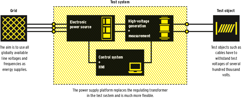
In order to explain just how big a step this is, this article intends to provide a brief overview of what the EPS does, how it differs from the current solution, and what innovations and customer benefits it brings with it. To achieve a test voltage of several hundred thousand volts, the available line voltage is converted to a much higher level via transformers. This works in a similar way to a primary substation used by a domestic energy supplier. To prevent the object that is the subject of the test from being destroyed, the output voltage needs to be regulated.
And there’s a little trick that can be used to do this, which involves regulation taking place straight away at the low-voltage side. The effect of the transfer ratio can then be seen at the output. To put it in simpler terms, if you have connected a system with a maximum voltage of 500,000 volts to a 400-volt grid and then set 200 volts at the input, there will be 250,000 volts at the output. Similarly, if 40 volts are set at the input, there will be 50,000 volts at the output, and so on.
Previously, a regulating transformer was used to achieve this. This mechanism conveys a current collector across the windings with the aid of a mechanical drive, adjusting the voltage from 0 to 400 volts as a result. The size of the structure used can vary significantly depending on the connected load and connection voltage. The supply grid is loaded asymmetrically on two of three phases.
It is at precisely these points that the EPS comes in. At the grid connection, there is an electronic power circuit—known as the active front-end—provided directly by colleagues at MR PQ. This is used to rectify the AC voltage from the grid and then feed it into a DC link capacitor. From there, a specially developed power inverter with IGBTs acting as semiconductor switches provides a variable, finely adjustable output voltage between 0 and 690 volts.
The grid load is distributed evenly across all three phases and the regulation procedure becomes much more precise and far faster—without the need for any mechanical moving parts. To prevent the need to manage lots of different designs, the rectifier and the power inverter can be connected in a modular manner, and the system can be scaled simply by changing the number of identical modules incorporated into the system.
Lower operating costs, shorter test times, simple expansion options, and quick and easy repairs — the new system delivers a whole range of benefits
This provides a whole host of benefits to customers. In addition to the more precise and faster voltage regulation that has already been described, excess energy in the resonant circuit can now be fed back from the corresponding testing systems to the power grid. Of particular interest is the variable system frequency, which can be set to between 0 and 500 hertz.
This enables our customers to perform tests for the entire global market using 50 hertz and 60 hertz—regardless of their actual location and the associated line frequency limits in different countries. Additional frequency variations can also be used to expand the test range or to take special measurements for the purpose of locating faults—measurements that were not possible previously. In addition, the system enables harmonics to be actively compensated or applied in specific ways.
Modular system
Essentially, the customer receives a system that can be extended as needed and will be well placed to meet whatever future demands it faces. What’s more, should there ever be a problem, the individual modules can be repaired quickly, meaning that the system will only be out of action for a few hours.
The modular design enables customers to benefit from the full range of functions that the system offers from the outset and upgrade it easily at any time. A whole host of properties that are currently delivered through add-on components come already integrated in the EPS, such as harmonic compensation, short-circuit detection, and emergency shutdown.
The supply platform is being introduced in stages. Facilities with a single-phase output voltage for AC systems of type WP (transformer-based) and type WRM (based on the resonance principle) will be the first to be equipped with the EPS. This will be followed by the adaptation for modular DC test equipment. The development of the three-phase EPS means that transformer test systems for low-voltage and medium-voltage transformers will soon be available with the new EPS feature too. The functions provided by the system are constantly being expanded.
Customer benefits
The biggest challenge when it came to developing the EPS was achieving a low noise level. Tests can only be done if what is known as the partial discharge background noise level is much lower than the signal being measured. The experts at HIGHVOLT have succeeded in reducing this noise level to < 1 pC (picocoloumb), meaning that it is below the level of conventional feed-ins.
Despite the extensive enhancements the EPS offers, it does not cost customers any more to purchase and even saves them money during operation thanks to shorter test times, simple expansion options, and quick and easy repairs. Not only that, but customers also benefit from a much wider range of functions that they can select based on their needs.
YOUR CONTACT

Do you have any questions about the electronic power source?
Martin Buschendorf is here to help:
M.Buschendorf@highvolt.com